Circuit Wiring Diagrams
The circuit wiring diagrams shown in this topic illustrate how the hot, ground, and/or neutral AC signals should be connected to the power input plugs of the ztC Endurance system and other components.
In the following diagrams, the power inputs for ztC Endurance systems are labeled X and Y, as shown in Figure 49 and Figure 50, to eliminate any ambiguities in the nomenclature. For single-phase applications, the X input is connected to the L (Line) hot input, and the Y input is connected to the N (Neutral) input. However, for split-phase or three-phase applications, the X and Y inputs are connected to L1, L2, or L3 (separate lines). Therefore, for split-phase or three-phase applications, both X and Y can be electrically hot with respect to the system base (earth reference ground).
Figure 49 shows a face view of the physical locations of the X and Y inputs on a customer-supplied PDU (either A or B).
Figure 49: PDU Power Input Labeling
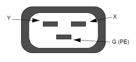
Figure 50 shows a face view of the physical locations of the X and Y inputs on a ztC Endurance system's PSU (either A or B).
Figure 50: ztC Endurance Enclosure Power Input Labeling
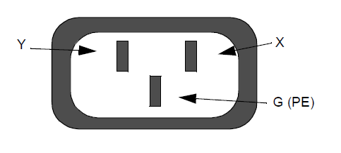
Figure 51 shows a single-phase 120V AC circuit connection. Note that this application requires a single-pole circuit breaker.
Figure 51: Single-Phase 120V AC Circuit Connection
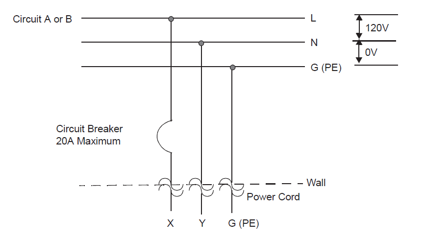
Figure 52 shows a single-phase 240V AC circuit connection. Note that this application requires a single-pole circuit breaker.
Figure 52: Single-Phase 240V AC Circuit Connection
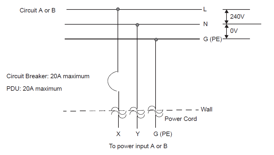
Figure 53 shows a split-phase 120/240V AC circuit connection. Note that this application requires a double-pole circuit breaker.
Figure 53: Split-Phase 120/240 Volts AC Circuit Connection
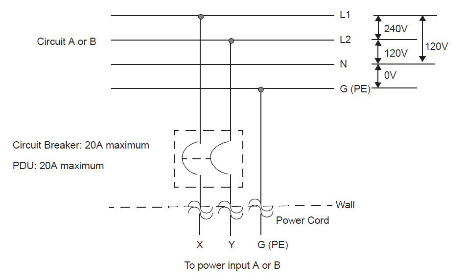
Figure 54 shows a three-phase 208V AC, Y-, or Δ-source circuit connection, which is a phase-to-phase source connection. Note that the X and Y inputs on the ztC Endurance system can be connected from L1 and L2, L2 and L3, or L1 and L3. This application requires a double-pole circuit breaker.
Figure 54: Three-Phase 208V AC, Y-, or Δ-Source Circuit Connection, Phase-to-Phase
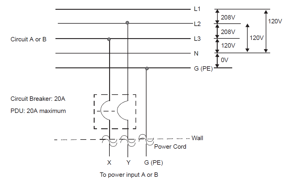
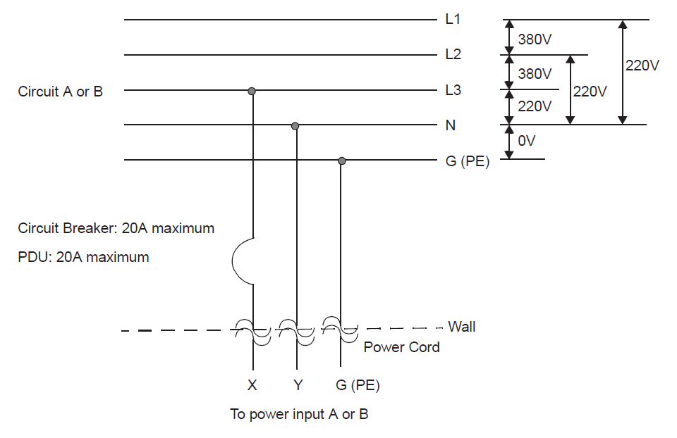
Figure 55 shows a three-phase 380V AC, Y-, or Δ-source circuit connection, which is a phase-to-neutral source connection. Note that the ztC Endurance system’s X input can be connected to L1, L2, or L3. This application requires a single-pole circuit breaker.
Figure 55: Three-Phase 380V AC, Y-, or Δ-Source Circuit Connection, Phase-to-Neutral