Connecting the System to Electrical Power
Connect the system to electrical power and fasten the power-cord retention strap as described in the following procedures.
-
A ztC Endurance 3100 system can operate in either the low-voltage or high-voltage range. Make sure you are using power cords that have the correct voltage range and that are rated for your country. If you are changing to a different voltage range, follow the instructions described in To replace both power cords.
- Both PSUs in a ztC Endurance system must operate in the same voltage range.
-
Le système ztC Endurance 3100 peut fonctionner en basse ou haute tension. Assurez-vous que vous utilisez des cordons d'alimentation dont la plage de tension est correcte et qui sont adaptés à votre pays. Si vous passez à une plage de tension différente, suivez les instructions décrites dans la section Pour remplacer les deux cordons d'alimentation.
- Les deux blocs d’alimentation d’un système ztC Endurance doivent fonctionner dans la même plage de tension.
For more information about electrical power planning, see Electrical Power Planning.
To connect the system to AC power mains
-
From the front and back of the system, make sure that all modules and power supply units (PSUs) are fully inserted.
-
Locate the two power cords for the system.
-
Connect the female end of the A-side power cord to the top PSU, as shown in Figure 21. Connect the other end to the A-side power source.
-
Connect the female end of the B-side power cord to the bottom PSU, as shown in Figure 21. Connect the other end to a second, separate, B-side power source.
-
Fasten the power-cord retention strap to each power cord as described in To fasten the power-cord retention strap.
Figure 21: Connecting a System Directly to AC Power
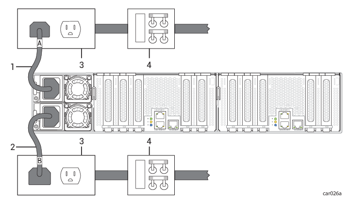
| 1 | A‐side power cord | 3 | AC power outlets |
| 2 | B‐side power cord | 4 |
AC power (mains) distribution circuit breakers (maximum of 20A) |
After connecting the system to electrical power, fasten the power-cord retention strap to each power cord to prevent unintentionally disconnecting the power cord from the system if the system is removed from the cabinet.
To fasten the power-cord retention strap
-
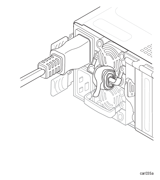
Locate the power-cord retention strap on PSU A, the upper PSU at the rear of the system, as shown in Figure 22.
Figure 22: Locating the Power-Cord Retention Strap
-
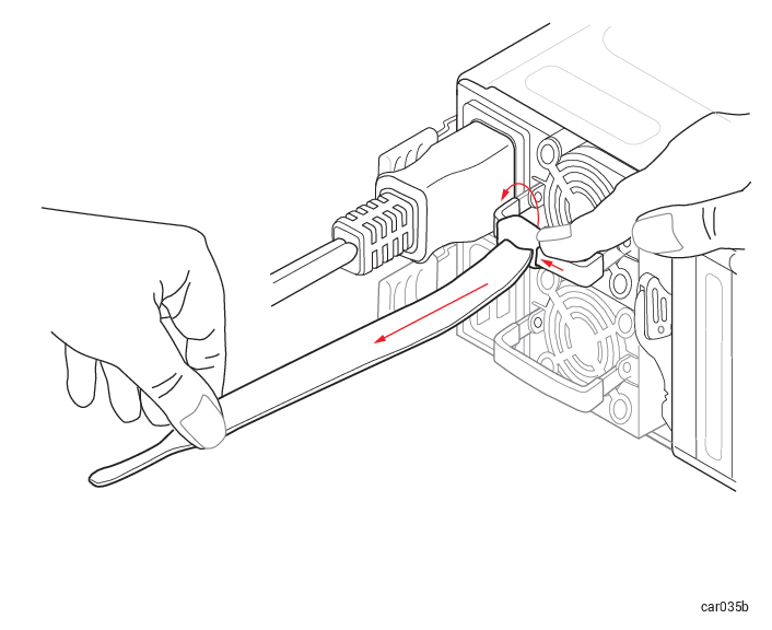
Pull on the end of the coiled strap to extend it, as shown in Figure 23.
Figure 23: Extending the Power-Cord Retention Strap
-
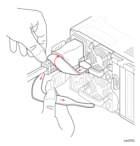
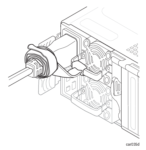
Wrap the strap tightly against the molded rib of the power cord to prevent the power cord from moving, as shown in Figure 24.
Figure 24: Installing the Power-Cord Retention Strap
-
Continue wrapping the strap around the power cord until the strap is tightly in place, as shown in Figure 25.
Figure 25: Correct Installation of the Power-Cord Retention Strap
-
Repeat this procedure on PSU B, the lower PSU.
To replace both power cords
-
Unwrap the power-cord retention straps, and then disconnect the power cords. See Figure 45.
-
Wait for all LEDs in the front and rear of the system to turn off, including the LEDs on both PSUs. All LEDs turning off indicates that the standby voltages have dissipated.
-
Replace the two power cords, using the correct power cords for the voltage being used, and fasten the power-cord retention straps.