Removing and Replacing a Compute Module
To remove a compute module
-
Place the compute module into maintenance mode as described in Using Maintenance Mode.
-
After the compute module is in maintenance mode, shut it down as described in Shutting Down and Restarting a Compute Module.
-
Disconnect all cables from the compute module.
-
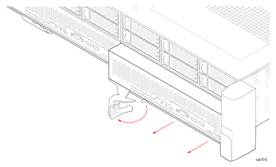
Use your index finger to unlatch the release lever on the compute module.
-
Grasp the release lever and pull it away from the system chassis until the module extends an inch or two from the system chassis. See Figure 30.
Figure 30: Removing Compute Module
-
Holding the module on each side, pull it straight out of the system chassis and place it on a flat, stable surface.
To replace a compute module
-
Check the Hardware Page of the ztC Endurance console to make sure that the compute module is in maintenance mode.
-
Extend the release lever on the compute module to the left until it is fully open.
-
Holding the compute module on each side, slide it into one of the bottom slots until it stops. Ensure that the module is fully seated and aligns with the system chassis.
-
Push on the center of the compute module with one hand while simultaneously using your other hand to push the release lever toward the system chassis until it clicks. See Figure 31.
Figure 31: Replacing Compute Module
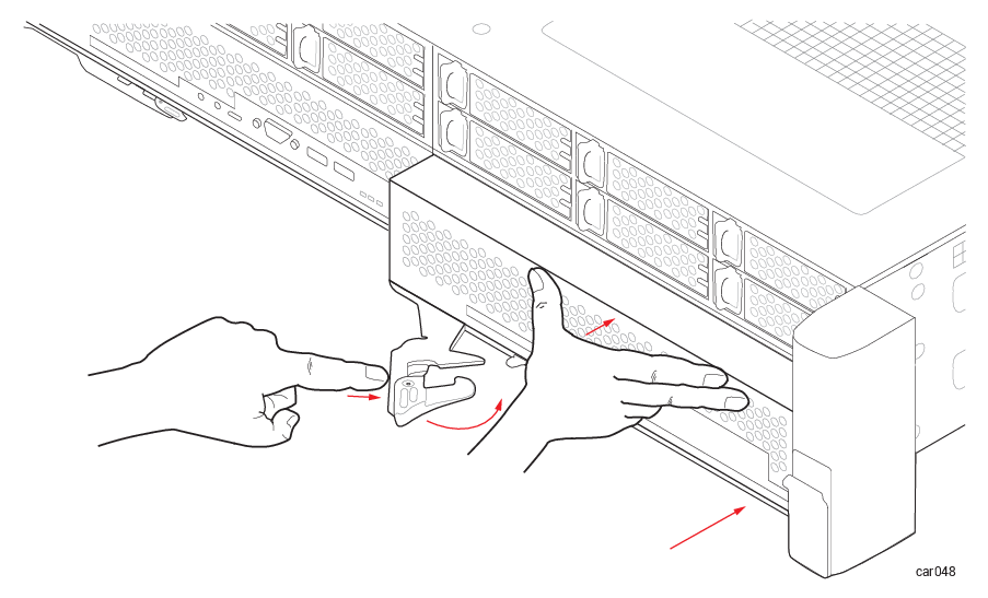
- Push on the center of the compute module once more to make sure it is fully seated in the system chassis.
-
Connect all of the cables.
-
Remove the compute module from maintenance mode as described in Using Maintenance Mode.
Notice: If you insert a replacement compute module but do not remove it from maintenance mode, the system software cannot update the BMC, BIOS, or Standby OS. The system software also posts an alert to indicate that it cannot update the standby compute module until maintenance mode is cleared.