Status LEDs
Status LEDs are located on the control-panel ear![]() A module located at the front right of the ztC Endurance system. It houses a USB 2.0 port, power button for the ztC Endurance system, and LEDs that indicate system power status (PWR), fault conditions (ATTN), and module identification status (UID). as well as the front of each CRU module. This topic illustrates and describes these LEDs. See Figure 28 and Figure 29, as well as Table 9, Table 10, Table 11, Table 12, and Table 13.
A module located at the front right of the ztC Endurance system. It houses a USB 2.0 port, power button for the ztC Endurance system, and LEDs that indicate system power status (PWR), fault conditions (ATTN), and module identification status (UID). as well as the front of each CRU module. This topic illustrates and describes these LEDs. See Figure 28 and Figure 29, as well as Table 9, Table 10, Table 11, Table 12, and Table 13.
You can use the ATTN LEDs to diagnose faults, as described in Using the ATTN LEDs to Diagnose Faults .
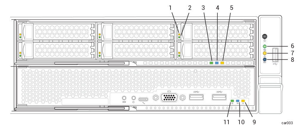
Figure 28: Front LEDs: Storage Module, Control-panel Ear, and Compute Module
| Callout | LED | State | Description |
|---|---|---|---|
| 1 | Fault | Off | Normal operation. |
| Solid amber | The disk is broken and safe to remove. See Removing and Inserting a Disk Drive. | ||
| 2 | ACT | Off |
For 6.4 TB disks, indicates that the disk is present but idle. |
| Solid green |
For 1.6 TB or 3.2 TB disks, indicates that the disk is present but idle. |
||
| Blinking green | Data is being written to or read from the disk. | ||
| 3 | PWR | Off | DC power and standby power to the module are off. |
| Solid green | DC power to the module is on. | ||
| Blinking green | Standby power to the system is on; DC power to the module is off. | ||
| 4 | UID | Off |
No request to identify module activated (normal operation). To identify, see Identifying a System or Component. |
| Solid blue | Request to identify module activated; LED illuminates with DC power or with standby power. | ||
| 5 | ATTN | Off |
Indicates one of two scenarios:
To determine which scenario is true, check the control-panel ear's ATTN LED. If that LED is not illuminated, no module in the system needs to be replaced. |
| Blinking amber |
Fault; safe to replace the module. LED illuminates with DC power or with standby power. To replace, see Removing and Replacing a Storage Module. |
| Callout | LED | State | Description |
|---|---|---|---|
| 6 | PWR | Off |
DC power and standby power to the module are off. To turn power on or off, press the power button on the control-panel ear or use the BMC. See System Power. |
| Solid green | DC power to any module is on. | ||
| Blinking green | Standby power is on; no module has DC power. | ||
| 7 | ATTN | Off |
Indicates one of two scenarios:
|
| Solid green |
Indicates one of two scenarios:
|
||
| Blinking amber |
The ztC Endurance Management VM is running, and one or more modules are not inserted or need replacement. Check LEDs of all modules to identify the module with a fault. For a list of modules, see System CRU Modules. Note: After a total system shutdown, the ATTN LED remains in the last state it was in until you remove and restore standby power.
|
||
| 8 | UID | Off |
No request to identify module activated (normal operation). To identify, see Identifying a System or Component. |
| Solid blue | Request to identify module activated; LED illuminates with DC power or with standby power. |
| Callout | LED | State | Description |
|---|---|---|---|
| 9 | ATTN | Off |
Indicates one of two scenarios:
To determine which scenario is true, check the control-panel ear's ATTN LED. If that LED is not illuminated, no module in the system needs to be replaced. |
| Blinking amber |
Fault; safe to replace the module. LED illuminates with DC power or with standby power. |
||
| 10 | UID | Off |
No request to identify module activated (normal operation). To identify, see Identifying a System or Component. |
| Solid blue | Request to identify module activated; LED illuminates with DC power or with standby power. | ||
| 11 | PWR | Off | The module's DC power is off, and the other compute module's DC power is on. |
| Solid green | The module has DC power (standby power is also on). | ||
| Blinking green | The system has standby power only. |
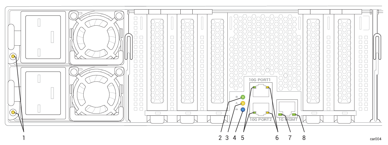
Figure 29: Rear LEDs: PSUs and I/O Module
| Callout | LED | State | Description |
|---|---|---|---|
| 2 | PWR | Off | DC power and standby power to the module are off. |
| Solid green | DC power to the module is on. | ||
| Blinking green | Standby power to the system is on; DC power to the module is off. | ||
| 3 | ATTN | Off |
Indicates one of two scenarios:
To determine which scenario is true, check the control-panel ear's ATTN LED. If that LED is not illuminated, no module in the system needs to be replaced. |
| Blinking amber |
Fault; safe to replace the module. LED illuminates with DC power or with standby power. To replace, see Removing and Replacing an I/O Module. |
||
| 4 | UID | Off |
No request to identify module activated (normal operation). To identify, see Identifying a System or Component. |
| Solid blue | Request to identify module activated; LED illuminates with DC power or with standby power. | ||
| 5 | 10 Gbps Link /ACT | Off | No link is present. |
| Solid green | Link is stable. | ||
| Blinking green | Data is being transferred over the link. | ||
| 6 | 10 Gbps Speed | Off | No link is present. |
| Solid green | Connection speed is 10 Gbps. | ||
| Solid amber | Connection speed is less than 10 Gbps. | ||
| 7 | 1 Gbps Link /ACT | Off | No link is present. |
| Solid green | Link is stable. | ||
| Blinking green | Data is being transferred over the link. | ||
| 8 | 1 Gbps Speed | Off | No link is present, or link speed is less than 1 Gpbs. |
| Solid green | Connection speed is 1 Gbps. |
Using the ATTN LEDs to Diagnose Faults
The ATTN LED on the control-panel ear and on the CRU modules help you diagnose faults. A fault is an issue that requires module replacement, as opposed to other types of errors that occur on a module (for example, correctable errors below a certain threshold) that do not require module replacement.
The examples in Table 14 provide more information about using the ATTN LEDs to diagnose faults.